


Available from:
Alza.de
Banggood.com
Aliexpress.com
Manufacturer:
Sonoff.tech
| GPIO # | Component |
|---|---|
| GPIO00 | Button1 |
| GPIO01 | User |
| GPIO02 | User |
| GPIO03 | User |
| GPIO04 | Relay3 |
| GPIO05 | Relay2 |
| GPIO09 | Button2 |
| GPIO10 | Button3 |
| GPIO12 | Relay1 |
| GPIO13 | Led1i |
| GPIO14 | Button4 |
| GPIO15 | Relay4 |
| GPIO16 | None |
| FLAG | None |
{"NAME":"Sonoff 4CH","GPIO":[17,255,255,255,23,22,18,19,21,56,20,24,0],"FLAG":0,"BASE":7}Serial Flashing
Please see the Getting Started page in Tasmota docs for general flashing instructions.
Sonoff 4CH and Sonoff 4CH R2 use the same configuration but have slightly different boards. Check which version you own before proceeding.
Sonoff 4CH
Attention: The printed labels on the PCB for RX and TX may be incorrectly swapped as can be seen on the image. Regardless of the labels, the pin next to VCC33 is RX.
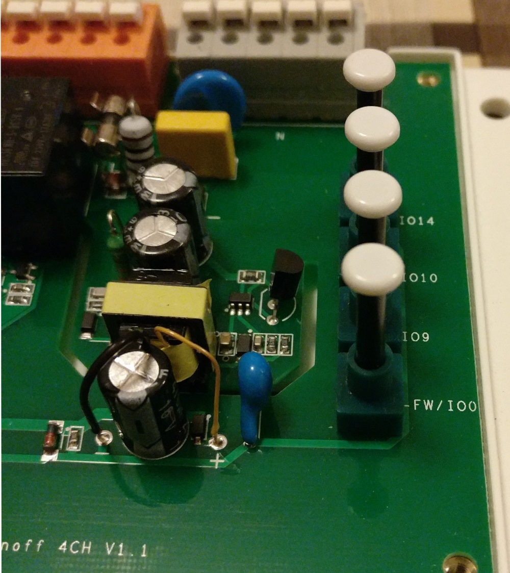
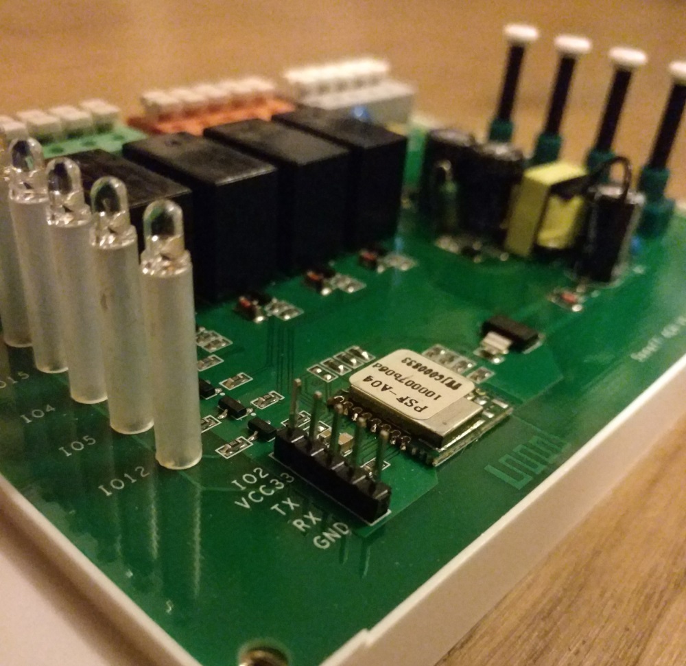 The Sonoff 4CH features four hardware buttons. Button marked FW/IO0 is connected to GPIO0 and can be used to bring the module into flash mode.
Sonoff 4CH R2
Board is labelled Sonoff 4CH R2 V1.0.
The RX and TX pins are correctly labelled on this PCB revision.
 The button labelled IO0 is connected to GPIO0 and can be used to bring the module into flash mode.
