


Available from:
Aliexpress.com
Banggood.com
Manufacturer:
Aihomestyle.com
| GPIO # | Component |
|---|---|
| GPIO00 | None |
| GPIO01 | Serial Tx |
| GPIO02 | None |
| GPIO03 | Serial Rx |
| GPIO04 | None |
| GPIO05 | None |
| GPIO09 | None |
| GPIO10 | None |
| GPIO12 | None |
| GPIO13 | Counter 1 |
| GPIO14 | PWM 1 |
| GPIO15 | None |
| GPIO16 | None |
| GPIO17 | None |
The Wi-Fi Smart Dimmer Module 150W is an in-wall push-button dimmer switch, manufactured by Aihomestyle Co LTD and sold as white-label QS-WiFi-D01-TRIAC and also by various brands e.g., Moes, MoesHouse MS-105, HomCloud, Malmbergs, TOOGOO, Baakey, …

Art. No. QS-WIFI-D01-TRIAC
- Trailing-Edge Phase Dimmer, definitely not TRIAC but Power MOSFET driven
- for dimmable LED light bulbs, dimmable power supplies, incandescent/halogen bulbs,…
Technical Data:
- Smart Wi-Fi Push-Button Dimmer Module
- Rated Voltage AC 220-240V / 50Hz
- Rated Current 0.6A
- Load max. 150W for LED lamp
- Size LxWxH 51mm x 47mm x 22mm
The Dimmer has a LM1 ESP8266 module with 1MB Flash onboard, combined with a STM8 MCU on a separate board.

Flashing Guide
OTA
This dimmer is based on Smart Life / Tuya App. Tuya-Convert currently works, but could be patched with future firmware updates.
Serial
- ⚠️️ Special Attention ⚠️️
- Do not connect AC power and the serial connection at the same time!
- The dimmer circuit is directly connected to the AC wires!
Follow all the recommended serial flashing procedures outlined in the Tasmota Flashing Guide.
The case can easily be opened by pressing both sides of the lower half of the case. One method to flash the device is to desolder the ESP/MCU module from the main PCB.

It’s also possible to flash the ESP8266 when the PCB is not desoldered, but it is a bit difficult to reach RX and TX.
To get the module into Flash Mode, you have to connect RE and GPIO0 to GND (RE to GND disables the STM8 MCU while flashing).


Configuration
Use the Template from above or set the module as Generic (18) and assign the following components:
| GPIO | Component |
|---|---|
| 1 | Serial Tx (148) |
| 3 | Serial Rx (149) |
| 13 | Counter1 (42) |
| 14 | PWM1 (37) (or any unused GPIO) |
See @anarchistdevop github for more info

Wiring Diagram:

The S switch input is intended for push-button / conventional momentary switch control and detects the mains frequency when the button is pressed. This makes it special and therefore it requires a Tasmota Script for ON/OFF and HOLD (long press) dimming operation.
Download script by thxthx0:
- Dimmer Script v2.0a for Tasmota 9.5+ (dimming stops when minimum or maximum brightness is reached)
- Dimmer Script v2.0a for Tasmota 9.5+ (changes the dimming direction when min/max brightness is reached and doesn’t stop dimming)
- Dimmer Script v1.0 for older Tasmota versions
To use the script, you need Tasmota with Scripting enabled. Download unofficial precompiled firmware from development branch.
Once the device is flashed with Tasmota, open Configuration -> Edit script in the web UI and paste the contents of the script in the window. Then set the script enable checkbox and push Restart.
To hide “Counter1” in the WebUI you can enter WebSensor1 0 on the Tasmota Console.
How it works:
Whenever the button is pressed there are 50/60 Hz pulses on the S switch input. The frequency detection circuit (below) is connected to GPIO13 of the ESP8266 chip.
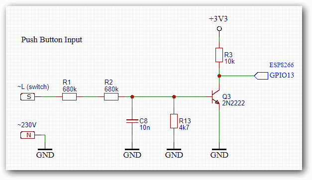
These pulses must be processed as a switching signal with a counter. The ESP8266 then sends commands accordingly via the hardware serial interface for dimming operation, which are handled by a second microcontroller (STM8S003F3 MCU). The serial communication at 9600 baud is simple, just one command with changing brightness xx values: FF 55 xx 05 DC 0A
What the Script does:
Switching in Tasmota is usually done by High/Low (+3.3V/GND) changes on a GPIO. Here, however, this is achieved by a pulse frequency when connected to a GPIO. These pulses are captured by Counter1 in Tasmota.
- When the light is OFF and there is a short period of pulses -> then turn the light ON at the previous dimmer level.
- When the light is ON and there is a short period of pulses -> then turn the light OFF.
- When there is a longer period of pulses (i.e., HOLD) -> toggle dimming direction and then adjust the brightness level as long as the button is pressed or until the limits are reached.
In the Data Section >D at the beginning of the script, the following initialization variables may be changed:
- dim step ->
1..5- sets the dimming increment value - dim multiplier ->
1..2.55- values lower than 2.55 reduce the dimmer range (100..255) - dim lower limit -> min
0- lower limit for the dimmer value for push-button operation (set according to your bulb) - dim upper limit -> max
100- upper limit for the dimmer value for push-button operation (set according to your bulb) - start dim level ->
0..100- initial dimmer level after power-up or restart
Further Information:
Support for Wi-Fi Dimmer? #5737
Switching by Mains Power Frequency #6085
Additional Pictures:


