


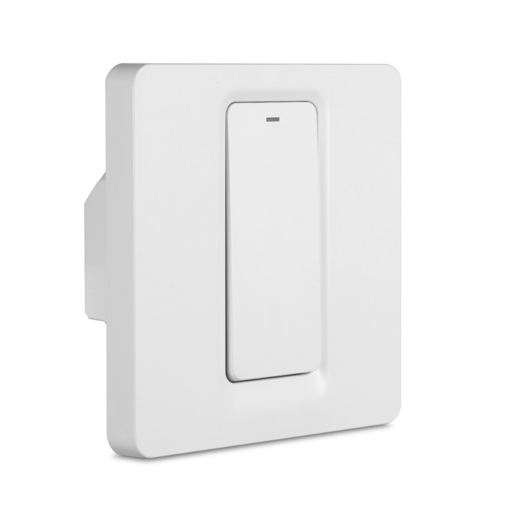
DS-102 1 Gang Switch
Available from:
Aliexpress.com
Amazon.de
Banggood.com
| GPIO # | Component |
|---|---|
| GPIO00 | LedLinki |
| GPIO01 | None |
| GPIO02 | None |
| GPIO03 | Button1 |
| GPIO04 | None |
| GPIO05 | None |
| GPIO09 | None |
| GPIO10 | None |
| GPIO12 | None |
| GPIO13 | Relay1 |
| GPIO14 | Led1 |
| GPIO15 | None |
| GPIO16 | None |
| FLAG | None |
Configuration (old format, will be converted to new template when applied)
{"NAME":"DS-102 1 Gang","GPIO":[158,0,0,17,0,0,0,0,0,21,52,0,0],"FLAG":0,"BASE":18}This device now comes with a Wi-Fi module incompatible with Tasmota
Warning
As of May 2022 these switches use a WB3S chip (BK7231T) and are no longer compatible.
The blue LED is configured to indicate switch state, the red LED is configured as link indicator. Switch the GPIOs to show switch state in red. If you prefer the switch state LED to be illuminated when power is turned OFF, i.e. when the room is dark, replace “Led1i” by “Led1”.