


Available from:
Alza.de
| GPIO # | Component |
|---|---|
| GPIO00 | None |
| GPIO01 | Serial Tx |
| GPIO02 | None |
| GPIO03 | Serial Rx |
| GPIO04 | User |
| GPIO05 | None |
| GPIO09 | None |
| GPIO10 | None |
| GPIO12 | None |
| GPIO13 | Led1i |
| GPIO14 | User |
| GPIO15 | None |
| GPIO16 | None |
| FLAG | None |
{"NAME":"Sonoff Dual","GPIO":[0,148,0,149,255,0,0,0,0,56,255,0,0],"FLAG":0,"BASE":5}Sonoff Dual has been obsoleted by Sonoff Dual R2. Before configuring your device check which revision you have since there are significant differences in how they operate.
Serial Flashing
Please see the Hardware Preparation page for general instructions.
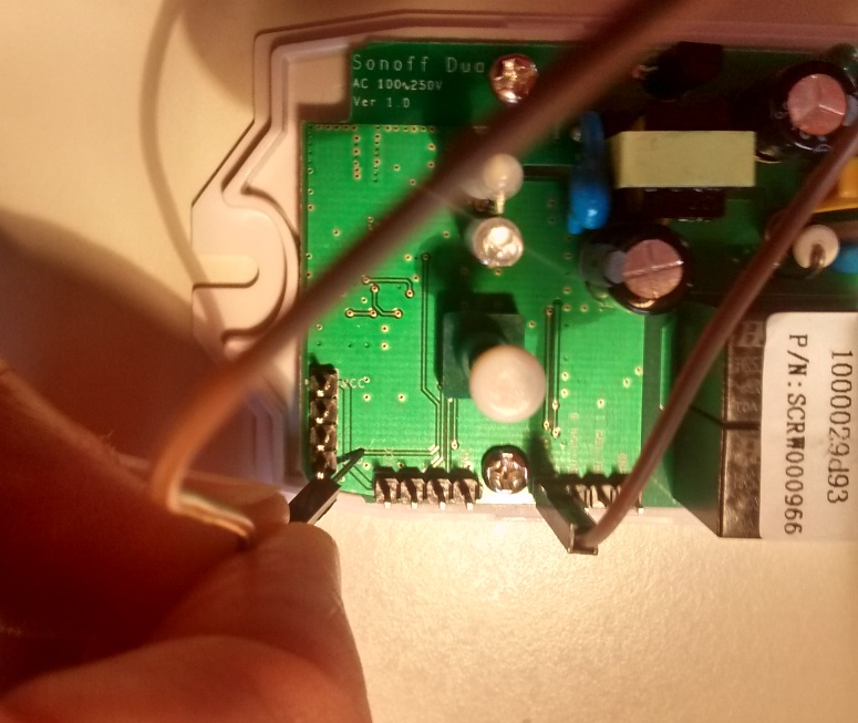
As always, you need to access the serial interface. The four serial pins (3V3, Rx, Tx, GND) are available at the short end of the PCB and can be seen on the left side of the first image and are labeled in red on the second image.
 Alternative GPIO locations
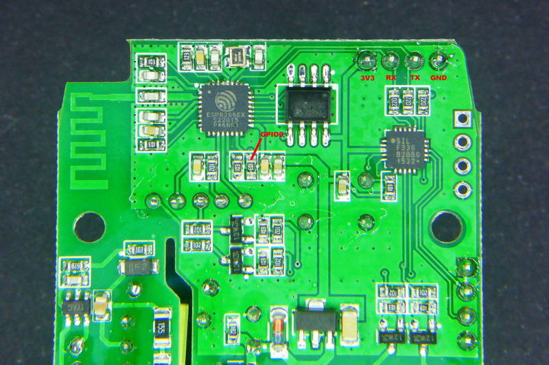
Programming the Sonoff Dual is more difficult because the on-board-button is not connected to GPIO0. As with all ESP8266 modules pulling GPIO0 to GND is needed to put the chip in programming mode. You need to connect GPIO0 and GND during power up.
GND can be found on all three headers. GPIO0 can be accessed in two ways:
- Unscrew the Sonoff Dual from the housing and access the underside of the PCB. You can find GPIO0 on one side of a resistor as shown in the second image.
- GPIO0 can be found on the small inter layer via pointed at in the first image. Attention: If the via is covered by silk screen (green) you need to expose the underlying conductive (copper) by carefully scratching it off.
Restricted Button Functionality
Please be aware, that the button on the Sonoff Dual will initially not have any functionality!
After configuring the device as “Sonoff Dual (5)”, the button will regain normal functionality.
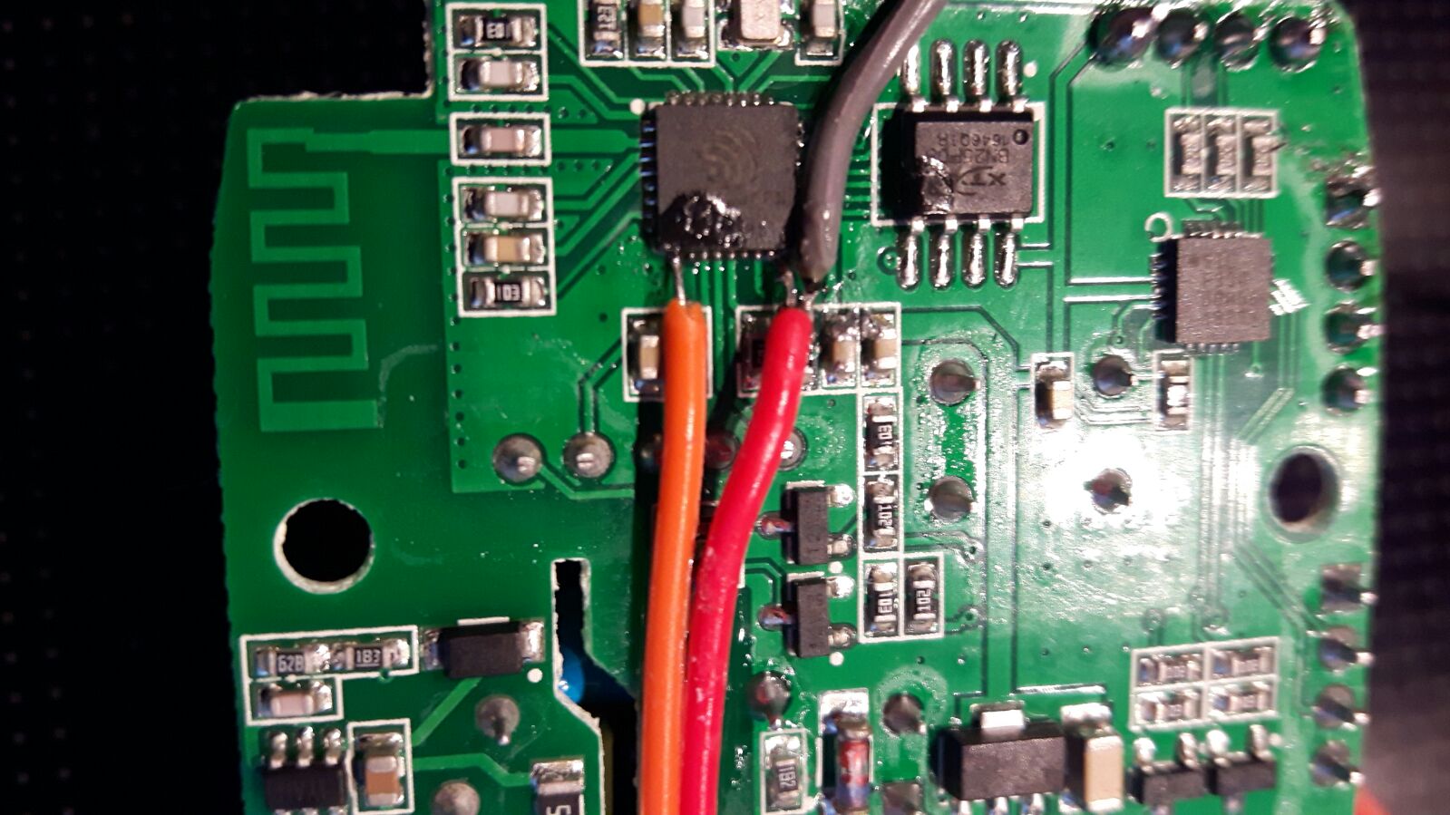
GPIO Locations
GPIO4 = red, GPIO14 = orange
Solving intermittent relay switch errors
Where most Sonoff’s use GPIO to control one or more relays the Sonoff Dual uses the serial interface to control the relays.
Commands are send from the ESP8266 via a 19200 baud serial connection to a dedicated chip that controls the relays.
It is therefore important to disable any serial communication to and from the device once you have debugged any anomalies.
To assist easy installation serial logging is enabled by default in Tasmota. For the Dual it is mandatory to turn it off withe SerialLog 0 comand.
Another reason for intermittent switching errors can be Power Saving. Make sure it is disabled by executing the command sleep 0.
Official Sources
- Itead Product Page: http://sonoff.itead.cc/en/products/sonoff/sonoff-dual
- Itead Shop: https://www.itead.cc/sonoff-dual.html
- Itead Wiki: https://www.itead.cc/wiki/Sonoff_Dual