


Available from:
Alibaba.com
Aliexpress.com
Walmart.com
Manufacturer:
Wiki.iteadstudio.com
| GPIO # | Component |
|---|---|
| GPIO00 | Button1 |
| GPIO01 | User |
| GPIO02 | None |
| GPIO03 | User |
| GPIO04 | None |
| GPIO05 | None |
| GPIO09 | None |
| GPIO10 | None |
| GPIO12 | Relay1 |
| GPIO13 | Led1i |
| GPIO14 | User |
| GPIO15 | None |
| GPIO16 | None |
| FLAG | None |
{"NAME":"Sonoff Basic","GPIO":[17,255,0,255,0,0,0,0,21,56,255,0,0],"FLAG":0,"BASE":1}Sonoff Basic - the one that started it all! This device is replaced by BASICR2.
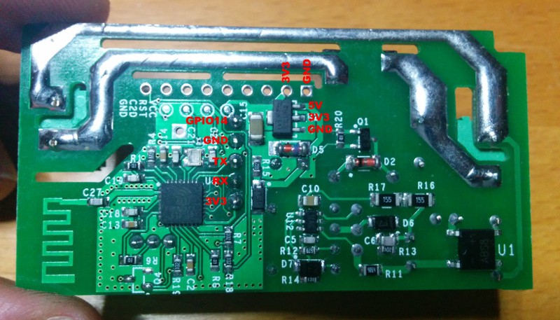
Board layout for original version of Sonoff Basic.
 (Image re-used from https://www.instructables.com/id/Use-Homie-Firmware-to-Drive-Sonoff-Switch-Module-E/ Thanks @amayii0)
- GPIO 03 - RX PIN
- GPIO 01 - TX PIN
- GPIO 14 - Below GND PIN
- GPIO 04 - Second image (must solder wire to pin on ESP chip)

Serial Flashing
Please see the Hardware Preparation page for general instructions.
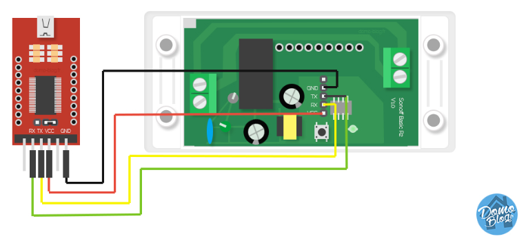
You need to access the serial interface. The four serial pins (3V3, Rx, Tx, GND) are available in the middle of the PCB, right next to the on-board button. The square pin right next to the button is the 3.3V line. Hold the button while powering to enter flash mode. The LED remains off until the flashing process is done and the board is rebooted.