


Available from:
Itead.cc
Domadoo.fr
Aliexpress.com
Mediarath.de
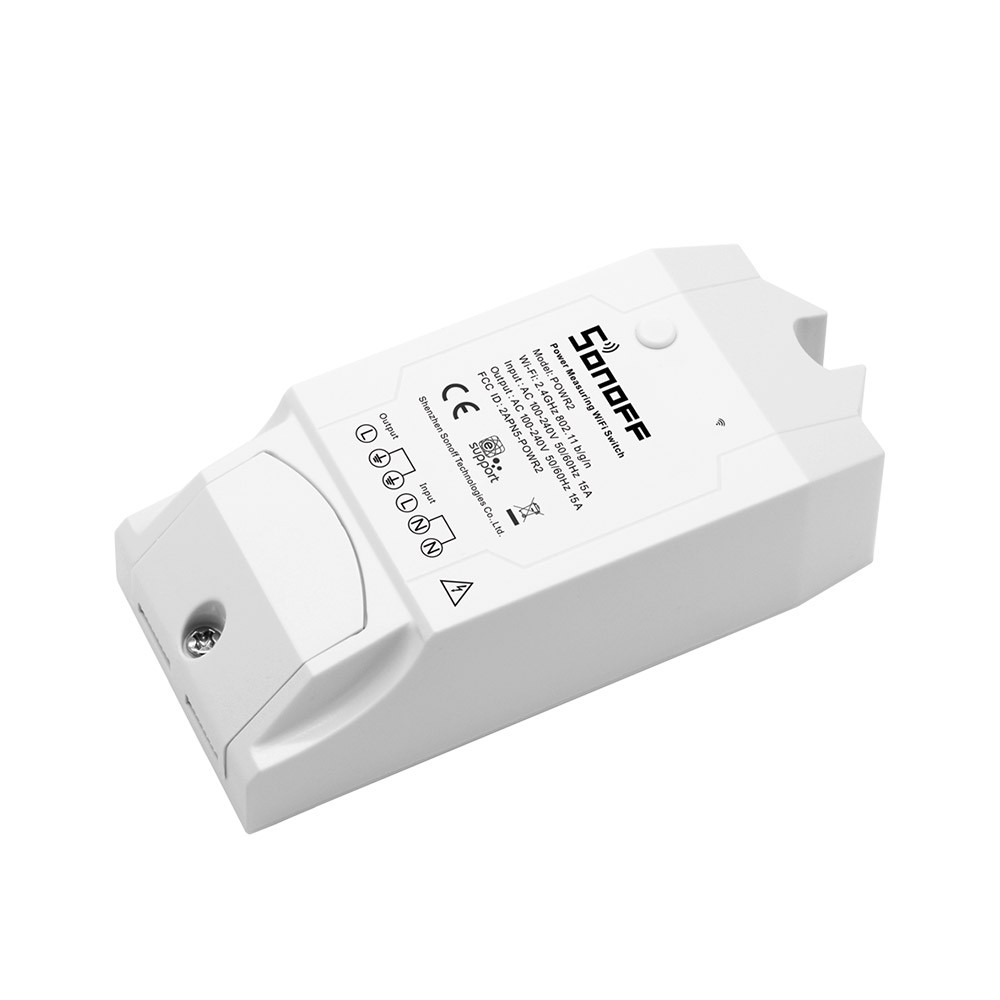
Manufacturer:
Sonoff.tech
| GPIO # | Component |
|---|---|
| GPIO00 | Button1 |
| GPIO01 | CSE7766 Tx |
| GPIO02 | None |
| GPIO03 | CSE7766 Rx |
| GPIO04 | None |
| GPIO05 | None |
| GPIO09 | None |
| GPIO10 | None |
| GPIO12 | Relay1 |
| GPIO13 | Led1i |
| GPIO14 | None |
| GPIO15 | None |
| GPIO16 | None |
| FLAG | None |
{"NAME":"Sonoff Pow R2","GPIO":[17,145,0,146,0,0,0,0,21,56,0,0,0],"FLAG":0,"BASE":43}Use code
BLAKADDER when buying from itead.cc for a 10% discount.
Use code BLAKADDER23 when buying from mediarath.de Tasmota category and a minimum order value of 50€ for a 10% discount. The code is valid until end of 2023.
Alternative template where the blue LED lights up only in case of connection issues and on button actions:
{"NAME":"Sonoff Pow R2","GPIO":[17,145,0,146,0,0,0,0,21,158,0,0,0],"FLAG":0,"BASE":43}
⚠️️Special Attention ⚠️️
Do not connect AC power and the serial connection at the same time The GND connection of the Pow is connected to the live AC wire. Connecting serial with your PC will fry your PC and will electrocute you.
DO NOT CONNECT ANY SENSORS TO THESE DEVICES!!! The GPIOs on the Pow are connected to AC power! Only use them as designed.
The AC connection between Pow and Pow R2 is different, please check exactly which version you have.
- Pow R2: Lo-E-E-Li-N-N = LineOut-EarthOut-EarthIn-LineIn-NeutralOut-NeutralIn
- Pow: Lo-E-E-N-N-Li = LineOut-EarthOut-EarthIn-NeutralOut-NeutralIn-LineIn
Serial Flashing
Please see the Hardware Preparation page for general instructions.
3V3, RX, TX and GND pins are available at the rear/short end of the PCB.

To enter flash mode, press down on the button while powering the device.
Some users have reported problems trying to flash this device. A possible solution is provided by i3laze in an issue. Placing a 220 ohm resistor between the VDD and RX connectors will solve the problem.
Note - After the module type is changed to “Sonoff Pow R2”, the serial port is no longer available for entering configuration commands because the serial port is used to communicate to the power measurement chip. Make sure you have set up your network connection before doing this.
Video tutorial by alsolh
Power Monitoring Calibration
Sonoff Pow R2 might need calibration as correct measurements are influenced by hardware and timing differences. See Power Monitoring Calibration
Telemetry
The Sonoff Pow R2 can provide Energy, Power, Voltage and Current information in different ways.
The preffered way is using the periodic telemetry data. Default setting TelePeriod 300 will send telemetry data every 5 minutes.
If the setting
PowerDelta(new since version 5.12.0e) is not 0 (default 80%), telemetry will be sent on power change too.
tele/pow1/SENSOR = {"Time":"2018-02-15T17:37:10","ENERGY":{"TotalStartTime":"2018-11-14T18:39:40","Total":6.294,"Yesterday":5.340,"Today":0.954,"Period":217,"Power":2635,"ApparentPower":2650,"ReactivePower":282,"Factor":0.99,"Voltage":227,"Current":11.661}}
To request information you can use command Status 8.
stat/pow1/STATUS8 = {"StatusSNS":{"Time":"2018-11-15T08:54:18","ENERGY":{"TotalStartTime":"2018-11-14T18:39:40","Total":6.404,"Yesterday":5.340,"Today":1.064,"Power":2629,"ApparentPower":2645,"ReactivePower":288,"Factor":0.99,"Voltage":226,"Current":11.677}}}
The presented information has the following meaning:
| Message | Unit | Description |
|---|---|---|
| TotalStartTime | Date | DateTime of calculation for Total |
| Total | kWh | Total Energy usage including Today |
| Yesterday | kWh | Total Energy usage between 00:00 and 24:00 yesterday |
| Today | kWh | Total Energy usage today from 00:00 until now |
| Period | Wh | Energy usage between previous message and now |
| Power | W | Current effective power load |
| ApparentPower | W | Power load on the cable = sqrt(Power^2 + ReactivePower^2) |
| ReactivePower | W | Reactive load |
| Factor | The ratio of the real power flowing to the load to the apparent power in the circuit | |
| Voltage | V | Current line voltage |
| Current | A | Current line current |