


Available from:
Amazon.de
Amazon.com
Domadoo.fr
Aliexpress.com
Idealo.de
Manufacturer:
Shelly.cloud
Install method:
MgOS to Tasmota
| GPIO # | Component |
|---|---|
| GPIO00 | User |
| GPIO01 | User |
| GPIO02 | None |
| GPIO03 | User |
| GPIO04 | Relay 1 |
| GPIO05 | Switch_n 1 |
| GPIO09 | None |
| GPIO10 | None |
| GPIO12 | None |
| GPIO13 | None |
| GPIO14 | None |
| GPIO15 | None |
| GPIO16 | None |
| GPIO17 | None |
{"NAME":"Shelly 1","GPIO":[1,1,0,1,224,192,0,0,0,0,0,0,0,0],"FLAG":0,"BASE":46}⚠️️Special Shelly Attention⚠️️
Do not connect AC power and the serial connection at the same time The GND connection of the Shelly has a 50% chance of being connected to the live AC wire. Connecting serial with your PC will fry your PC.
Do not connect any additional sensors to serial pins. It can at least destroy your Shelly!
Check the correct jumper position before connecting AC power to Shelly 1. If the jumper is set to 12V you will destroy your Shelly!
An ESP8266 with 2MB flash single relay device 42mm “round” in size.
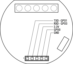
Serial Connection
Shelly1 comes with a partially exposed programming/debug header which can be used to flash Tasmota on the device. A serial-to-USB adapter is needed as well as a reliable 3.3V source with at least 350 mA drive capability. The following diagram shows the device pinout.
Flash mode
To be able to flash the Tasmota firmware you need to get into flash mode. Therefore connect a wire from GPIO0 to ground. For further information have a look at Hardware Preparation.
⚠️️WARNING⚠️️
Please note what version of the Shelly 1 you have (V1, V2 or V3). The V2 user guide is incorrect. The mains connections are as shown in the image above for all versions of the switch. The labels on the V2 switches are wrong!